Few improvements and corrections in the new version [ 1180415 ]. Measurements simulator: front baffle characteristic is applied also on the LF response. “Recent" submenu was added in the "File" menu for easy re-opening previous works and experiments. Circuit price calculation: when moving mouse over a design node, the price appears in the status bar. This works only if all of the elements included in the circuit have price defined (check your components lists), otherwise it is displayed as "n/a". Remember to use the same currency for all elements when creating lists of components for a design. Price calculation feature made me think of an idea to include circuit price reduction as an additional (optional) goal for the automatic designer. Maybe it will appear in one of the next versions
Posty
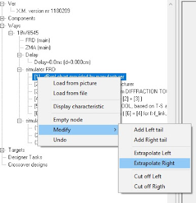
New version of XMachina: [ 1180209 ]. An option to digitize impedance characteristics in logarithmic scale has been added to the axis definition window. (For example Scan-Speak data datasheets use logarithmic impedance charts). Few simple tools have been implemented in the measurement simulator, supporting to estimate characteristics outside the loaded range. The characteristics can be “tailed” with a specified slope or extrapolated with a slope calculated from the characteristic shape at the edge. In case of impedance characteristics, values of DC resistance (Re) and voice coil inductance (Le) can be utilized for the estimation (Re for low and Le for high frequency range). Estimation improves the accuracy of phase calculation. It was used also in the previous version but only as an “on the fly” action during the acceptance of measurements simulator results.

XMachina has now a measurements simulator. Check out the new version [ 1180114 ] Take measurements whenever you can. But if for any reason you can not - try measurements simulator. The quality of the simulator results depends on several factors: - precision and reliability of manufacturer data, - accuracy of computer models predicting baffle diffraction and enclosure bass response - consistency of XMachina measurements simulator procedure (which has not yet been proven in practice). It's possible to use any diffraction and bass response tools with XMachina. It can cooperate with the tools via easy to use "chart picture" interface. You can configure shortcut keys for starting these tools when working with XMachina. Using the simulator: complete dedicated subnodes with relevant data one by one. When you get to the last node, choose "Apply result" from the menu. From that moment your simulation will be available for automatic crossover design. . ...
3-way crossover design example with XMachina.

Another XMachina demo has been uploaded to YouTube: 3-way crossover design example. LINK It's divided into short videos covering the following steps: loading components ( link ) loading measurements ( link ) target dBspl and cross points setup ( link ) task setup ( link ) design process ( link ) inspecting results ( link ) Drivers applied: Tweeter: Dayton DC28F ( link ) Midrange: Dayton RS180P ( link ) Woofer: Dayton RSS265HF ( link ) There are 4 coils, 7 capacitors and 6 resistors in the result circuit. System dBspl characteristic of the design fits the target with c.a. +-2dB tolerance margin: Design process shown in the demo is only a software functionality presentation. The files used are not suitable for application in a real design, as they reflect the "infinite baffle" conditions. Nevertheless, they are great for playing and experimenting with XMachina. The project file is available here: link ...

In addition to the PS220 correction circuit design example, here is a comparation of two different results. The first one is from the YT demo ( Link ). It has two coils, two capacitors and it fits within c.a. +-3.5dB tollerance margin. The second one was designed with loosening part reduction strength, it has four capacitors, four coils but it is only a fraction of dB out of the target spl. The question if such a precise circuit is worth implementing remains open. However it's possible to design it with XMachina. spls: orange: driver, green: driver+simpler circuit (2xL, 2xC), gray: driver+precise circuit (4xL, 4xC) electrical transmitances: green: simpler circuit (2xL, 2xC), gray: precise circuit (4xL, 4xC), orange: driver spl
A Full Range design example having only a screenshoot of characteristics
An example of a circuit design from scratch for a Full Range system having only a screenshoot of frequency and impedance characteristics. FR Driver employed: Dayton PS220. A real design should of course take into account influence of the box. This is just an example of how to work with XMachina. (8-min screen record)